Re: Replacement key
Ok I found it, stored on my hard drive. :dance:
I can take no credit for this modification, but can say it works- as i have followed the instructions and now have electric locking on my tailgate.  artycheer:
below is the instructions created by Gordynismo, hopefully i have loaded them on to here as should be, if not please let me know so i can correct any postions of photos, instructions. thanks
:clappy: :thumbleft: :cheers2: :thumbright: :clappy: :thumbleft: :cheers2: :thumbright: :clappy:
I came home from work and did a short write up. If anyone has any questions just let me know. Please do not PM me. The odds are the quesiton that you have someone else might have as well. Please enter all questions in this post.
Thanks.
gordynismo
2005 Nissan Frontier Tailgate Lock
This modification to the tailgate allows the keyless entry as well as the inside door lock switch to control and aftermarket door lock actuator that is added to the tailgate.
***Use these instructions at your own risk. I can not nor do I assume any liability for any installation errors that might occur***
Parts List: Total Cost Approximately $40
(1) Door Lock Actuator Kit -
(2) Bosch Relays
10 AMP fuse and Fuse Holder
Crimp Connectors
30 FT – Black ¼” Wire Loom
30 FT – Dual Lead Black and Red Wire (at least 18 GA)
(2) Grommets (3/4” OD and ½” ID)
Wire Ties
STEP 1 – Removing Sill and Kick Plates
Remove the driver’s side sill panel. Lift the back of the panel and pull up while moving forward under the panel. This panel will pop off pretty easily.
Next pull the kick panel away from the door sill wall and remove the press on clip in the back that is located above the dead pedal.
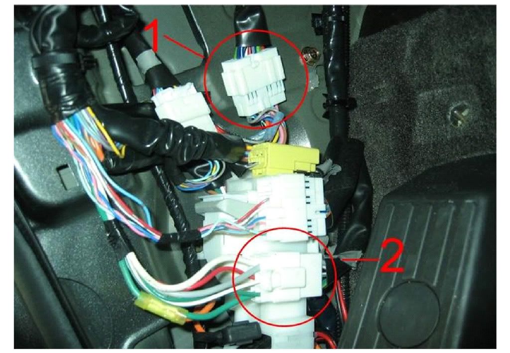
STEP 2 – Locating the Door Lock and 12 Volt Source Wires
Locate the wire door lock motor side harness that goes into the driver’s side door (1) and the steering column wire harness (2)
Push up on the door lock wire harness (1) molex and twist it around to reveal the back side. Locate the 16 GA Purple (Lock) and Grey (Unlock) wires. These wires will be spliced into to go to the 2 Bosch relays.
In the steering column harness (2) locate the 10GA green wire. This wire will be used for constant 12 volts and is the power source fuse holder and relays.
STEP 3 – Wiring Guide to the Relays
Splice into the door lock/unlock and power source wires by the diagram below. Use the 30 FT Dual Lead Black and Red Wire to connect the relays to the door lock actuator.
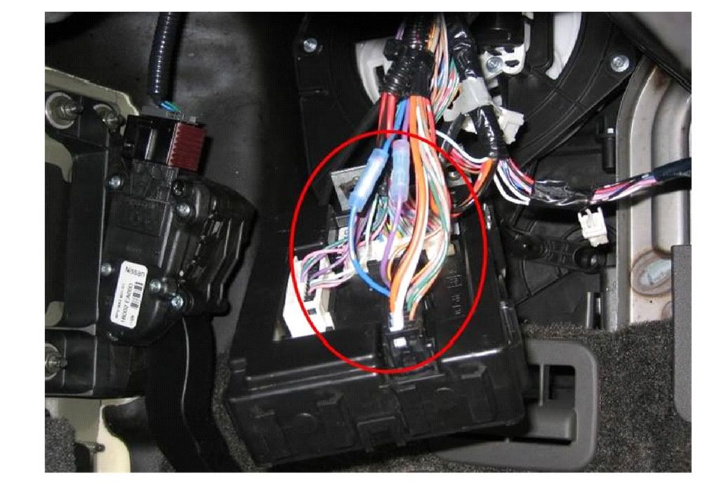
Also, the below pic is the BCM. It is located to the top right of the steering column and held on with 2 10mm bolts. These are kind of tough to get to but once they are removed it is a lot easier to work with. Locate the large black molex and find the purple wire (lock) and the blue wire (unlock of 2 presses of the keyfob); both wires are 18 GA,
STEP 4 – Running the Wire to the Tailgate
Make a small slit in the main harness grommet in the upper firewall that goes to the engine compartment.
Run the dual lead wire that should already be loomed along the chassis rail and back to the tailgate down the driver’s side of the truck.
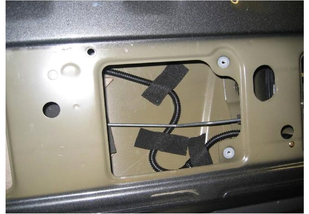
Step 5 – Getting the Wire into the Tailgate
Remove the paneling from the inside of the tailgate. Drill a ¾” hole in the bottom of the bed lip and another in the tailgate. Make sure the holes are offset a few inches. This will ensure that there will be minimal binding of the wire. Install the grommets.
Run the wires through the tailgate and use duct tape to hold the loom down. Make sure that the rods extending to the tailgate latches are not obstructed and can freely move.
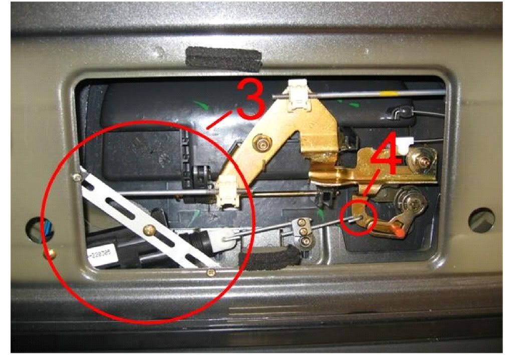
Step 6 – Adding the Door Lock Actuator
Mount the door lock actuator (3). Use your creativity. As long as the metal plate can still go back on and the actuator does not obstruct any linkage or tailgate handle movement everything should be OK.
Drill a 3/16” hole in the lock arm. This will allow a spot to attach the actuator rod. You will want to make sure the door lock actuator and hole drilled are slightly off center. This will allow the joining piece to be adjusted for movement back and forth
Step 7 – Connect the Wires.
Connect the door lock wires form the dual lead in the tailgate. Test the before you reassemble the tailgate paneling. If the lock work the opposite of the keyless entry just switch the wires on the actuator. This will reverse the polarity and should correct the backwards locking and unlocking.
__________________